MARC 155B CNC Instructions: Difference between revisions
mNo edit summary |
Admin boerj2 (talk | contribs) (GCode Generation Instructions) |
||
| Line 1: | Line 1: | ||
=== G-Code === | == G-Code Setup == | ||
The CNC Mill's in MARC can utilize G-Code Generated from Fusion or V-Carve Pro. This | |||
=== G-Code Generations === | |||
The CNC Mill's in MARC can utilize G-Code Generated from Fusion or V-Carve Pro. Only FUSION will be covered on a '''HIGH''' level overview. | |||
==== Requirements: ==== | |||
A login to Autodesk is required for this setup and configuration with an active subscription on the account. | |||
# A design that is in a FUSION 360 compatible format. Step files are recommended for transfers from other software like SolidWorks or Siemens NX | |||
# Known material properties | |||
# List of known CNC Bits that will be used. ''*Note: A single example will only be provided in the example below'' | |||
==== Fusion 360 Configuration ==== | |||
In the design area, load the part. ''It is recommended but not required to align the part with the expected axis during import.'' | |||
Instructions to load a part can be found here: [https://www.autodesk.com/support/technical/article/caas/sfdcarticles/sfdcarticles/How-to-import-or-open-a-file-in-Autodesk-Fusion-360.html How to load parts into Fusion] | |||
Full Fusion instructions for learning the <u>FUNDAMENTALS of MILLING</u> can be found here: [https://www.autodesk.com/learn/ondemand/curated/milling-basics?contextId=AP-C-FUNDAMENTALS-OF-MILLING Autodesk Learning - On Demand Milling Basics] | |||
===== Model Setup ===== | |||
# In the document settings, ensure that the units is set to mm | |||
# For each of the '''bodies''' set the material by: | |||
## Right click on the body | |||
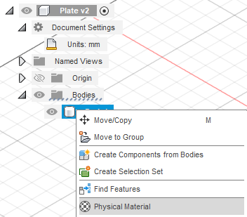
## Select ''Physical Material'' [[File:Fusion 360 Material Body Selection .png]] | |||
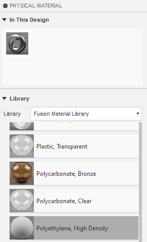
## Choose the material that will be used i.e. ''Polyethylene, High Density'' [[File:Fusion 360 HDPE Material Selection.png]] | |||
## Drag the material to the material onto the body | |||
===== Milling setup ===== | |||
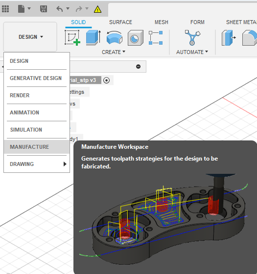
From the dropdown select '''Manufacture''' | |||
[[File:Fusion 360 Configuration Dropdown.png]] | |||
====== Machine Import ====== | |||
# Select Machine Library from the manage section in the ribbon by either clicking on the dropdown and selecting ''Machine Library'' or by clicking the icon that looks like a machine (2nd from the left in the screenshot below) [[File:Fusion 360 Machine Library Selection Item.png]] | |||
# In the machine library, select the Autodesk library | |||
# Check the box in the filter section to select the ''Milling'' capability | |||
# Find the Autodesk Generic 3-axis router, or similar 3 axis mills where the description indicates that <u>XYZ axis on the Head</u> [[File:Fusion 360 Machine Library mill selection.png]] | |||
# Drag the machine to the '''My Machines - Local''' library | |||
# Select the name and location of the '''CURRENT''' project to save the model to. [[File:Fusion 360 Model Download save location.png]] | |||
# The machine should now be in the local machine library. Click on close. [[File:Fusion 360 Local Machine library.png]] | |||
====== Machine Setup ====== | |||
Each setup is used to individually indicate a physical setup that will be done and where the system is referencing the co-ordinates. Only the general G54 home position will be used and explained in the documentation below. Use of secondary, tertiary and other coordinates are out of the scope of this configuration and setup. | |||
# Right click on Setups and select New Setup [[File:Fusion 360 Machine Setup - Operational.png]] | |||
# In the ''Setup tab'', select the machine from earlier in the Machines option by clicking on ''Select'' in the ''Machine'' section [[File:Fusion 360 Machine Setup - Selection.png]] | |||
# Click on the '''My Machines - Local''' library and highlight the imported machine. | |||
# Click on Select button (NOT Close). This will select the machine and allow for simulations. | |||
# On the ''Stock tab'', in the S''tock'' section, click on the mode dropdown and select '''Fixed size box''' [[File:Fusion 360 Machine Setup - Model Sizing.png]] | |||
# Enter the MEASURED size of the stock in, and select your reference point where you want to cut the part out of. For accuracy of the model, the center is recommended. | |||
# <u>DO NOT CLOSE THE SETUP CONTINUE BELOW</u> | |||
Only complete the items below if you need to correct the model orientation in the machine. | |||
# Back in the S''etup tab,'' in the ''Work Coordinate System (WCS)'' click on orientation [[File:Fusion 360 Machine Setup - Model orientation config.png]] | |||
# Select the '''known''' axis that aligns with the model that you have in your physical setup. X & Y is usually easiest as you can align that with the machine x and y coordinate directions | |||
# for each of the axis, select the corresponding item on the model by either selecting a known line, face or feature that aligns in the correct plane for the model and axis [[File:Fusion 360 Machine Setup - Model Axis selection.png]] | |||
# Select the G54 location on the model/stock in a known accessible location by clicking on one of the white dots on the '''STOCK BOX POINT''' [[File:Fusion 360 Machine Setup - G54 selection with axis alignment.png]] | |||
# Click on '''OK''' | |||
Only complete the below if the model is already in the correct axis alignment. | |||
# Ensure that the Origin Selection is set to '''Stock Box Point''' | |||
# Select the Stock point by clicking on one of the white dots on the stock box point. [[File:Fusion 360 Machine Setup - G54 with model configuration.png]] | |||
# Click on '''OK''' | |||
You should now have your model on the machine and a setup shown in the setups | |||
[[File:Fusion 360 Machine setup - Completed with G54 set.png]] | |||
====== Creating a tool and an operation ====== | |||
For this operation, a simple example of clearing a single pocket will be showcased. | |||
# Select the 2D Operations dropdown and select 2D Pocket [[File:Fusion 360 Machining Operation - 2D Pocket Selection.png]] | |||
# In the ''Tool tab'' and the ''tool section'', click on ''Select'' to create a new tool [[File:Fusion 360 Machining Operation - Tool Selection.png]] | |||
# Using the list that you had created earlier find the tool that you want to use | |||
# Select the '''Fusion Library''' - '''Milling tools''' from the menu on the left and turn on the library if required [[File:Fusion 360 Machining Tool library selection.png]] | |||
# In the filters on the right, select the correct type of mill that you want to create the operation for i.e. ''Flat End Mill'' | |||
# Find and select the correct milling bit that you are creating the operation with. '''IT IS HIGHLY RECOMMENDED THAT YOU MEASURE YOUR MILL BIT TO ENSURE YOU HAVE THE RIGHT SIZE.''' [[File:Fusion 360 Milling Bit selection .png]] | |||
# In the cutting data section select the correct material and operation type that will be completed. [[File:Fusion 360 Machining Speeds and Feeds defaulting.png]] | |||
# Click on Select | |||
# Change the coolant type to ''Disabled'' from the default that reads ''Flood'' [[File:Fusion 360 Machining Coolant Change.png]] | |||
# In the ''Geometry Tab'' under the ''Geometry section'', click on ''Select.'' | |||
# Click on the model feature that needs to be machined [[File:Fusion 360 Machining Pocket Selection.png]] | |||
# In the ''Heights Tab'', check that the clearance height is '''at least''' clearing the fixture mounting hardware. Screws through the materials should be fine with a 10mm clearance. [[File:Fusion 360 Machine clearance heights for fixturing.png]] | |||
# In the ''Passes Tab'' under the ''Stock to Leave'' option, take note of the stock that is left for '''Roughing passes'''. This should not be selected for finishing passes. [[File:Fusion 360 Roughing vs Finishing stock to leave.png]] | |||
# In the ''Passes Tab'', under the ''Multiple Depths'' section, based on the chip per tooth and loading of the bit, select the option and setup the appropriately calculated depth step down. [[File:Fusion 360 Machining Step down selection.png]] | |||
# Confirm that the toolpath generated successfully and that the operation is completed without any issues by reviewing the list of steps under the setup menu. [[File:Fusion 360 Setup Action confirmation.png]] | |||
====== G-Code Posting ====== | |||
Once all operations are completed to post the G-Code | |||
# Under the Actions Section in the ribbon, select the dropdown and choose Post Process option or click on the G1G2 icon. [[File:Fusion 360 Post Process configuration Selection.png]] | |||
# Under the ''Machine and Post'' section, click on the open folder icon under the ''Post'' section | |||
# Click on '''Fusion Library''' | |||
# In the Search Bar at the top search for <u>mach4</u> | |||
# Select '''Mach4Mill''' and click ''Select'' [[File:Fusion 360 Mach 4 Mill post processor selector.png]] | |||
# Click on the 3 dots to save to your local library similar to when the machine was downloaded [[File:Fusion 360 Local Post Library Folder.png]] | |||
# Click on Select Folder | |||
# Click on Copy to My Posts | |||
# Under the ''Program Section'' provide a numbered name only. It is highly recommended that you name your project in the format like in the table below. This will result in a unique number of the format 10010301 that is easily identifiable | |||
{| class="wikitable" | |||
|+ | |||
!Setup | |||
!Part | |||
!Group | |||
!Revision | |||
|- | |||
|xx | |||
|xx | |||
|xx | |||
|xx | |||
|- | |||
|10 | |||
|01 | |||
|03 | |||
|01 | |||
|} | |||
# | |||
=== Avid CNC Software === | === Avid CNC Software === | ||
Revision as of 12:34, 11 November 2024
G-Code Setup
G-Code Generations
The CNC Mill's in MARC can utilize G-Code Generated from Fusion or V-Carve Pro. Only FUSION will be covered on a HIGH level overview.
Requirements:
A login to Autodesk is required for this setup and configuration with an active subscription on the account.
- A design that is in a FUSION 360 compatible format. Step files are recommended for transfers from other software like SolidWorks or Siemens NX
- Known material properties
- List of known CNC Bits that will be used. *Note: A single example will only be provided in the example below
Fusion 360 Configuration
In the design area, load the part. It is recommended but not required to align the part with the expected axis during import.
Instructions to load a part can be found here: How to load parts into Fusion
Full Fusion instructions for learning the FUNDAMENTALS of MILLING can be found here: Autodesk Learning - On Demand Milling Basics
Model Setup
- In the document settings, ensure that the units is set to mm
- For each of the bodies set the material by:
Milling setup
From the dropdown select Manufacture
Machine Import
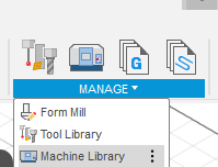
- Select Machine Library from the manage section in the ribbon by either clicking on the dropdown and selecting Machine Library or by clicking the icon that looks like a machine (2nd from the left in the screenshot below)
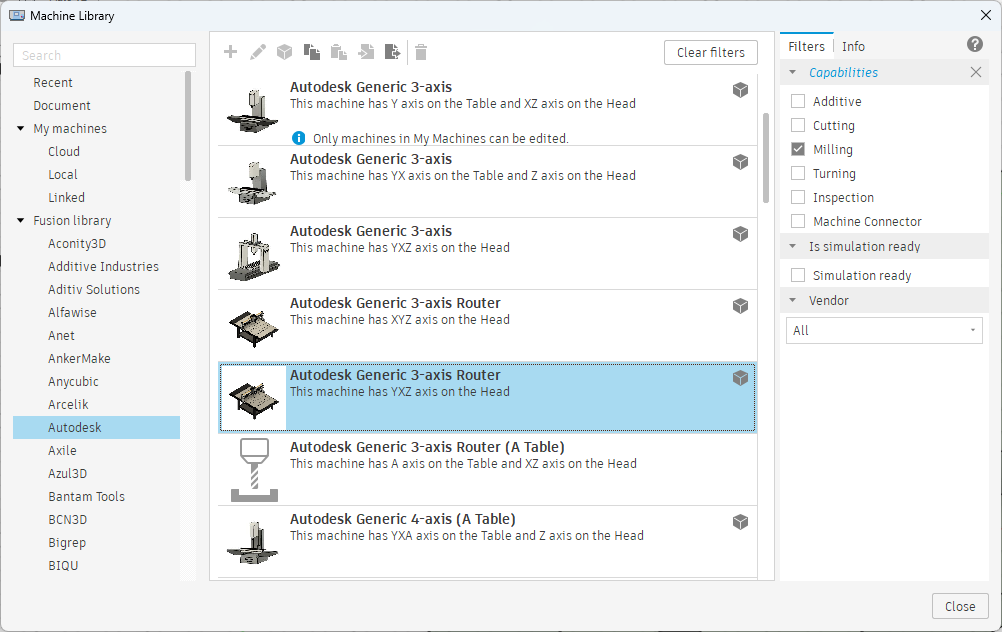
- In the machine library, select the Autodesk library
- Check the box in the filter section to select the Milling capability
- Find the Autodesk Generic 3-axis router, or similar 3 axis mills where the description indicates that XYZ axis on the Head
- Drag the machine to the My Machines - Local library
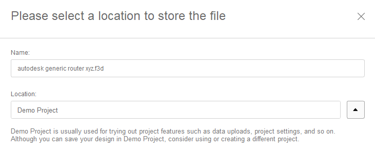
- Select the name and location of the CURRENT project to save the model to.
- The machine should now be in the local machine library. Click on close.

Machine Setup
Each setup is used to individually indicate a physical setup that will be done and where the system is referencing the co-ordinates. Only the general G54 home position will be used and explained in the documentation below. Use of secondary, tertiary and other coordinates are out of the scope of this configuration and setup.
- Right click on Setups and select New Setup

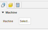
- In the Setup tab, select the machine from earlier in the Machines option by clicking on Select in the Machine section
- Click on the My Machines - Local library and highlight the imported machine.
- Click on Select button (NOT Close). This will select the machine and allow for simulations.
- On the Stock tab, in the Stock section, click on the mode dropdown and select Fixed size box
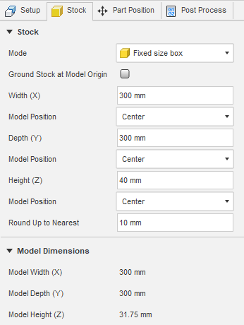
- Enter the MEASURED size of the stock in, and select your reference point where you want to cut the part out of. For accuracy of the model, the center is recommended.
- DO NOT CLOSE THE SETUP CONTINUE BELOW
Only complete the items below if you need to correct the model orientation in the machine.
- Back in the Setup tab, in the Work Coordinate System (WCS) click on orientation
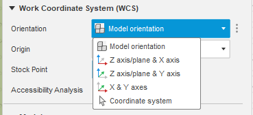
- Select the known axis that aligns with the model that you have in your physical setup. X & Y is usually easiest as you can align that with the machine x and y coordinate directions
- for each of the axis, select the corresponding item on the model by either selecting a known line, face or feature that aligns in the correct plane for the model and axis
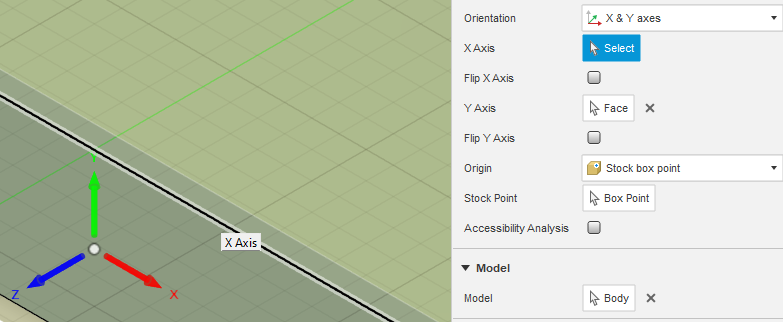
- Select the G54 location on the model/stock in a known accessible location by clicking on one of the white dots on the STOCK BOX POINT
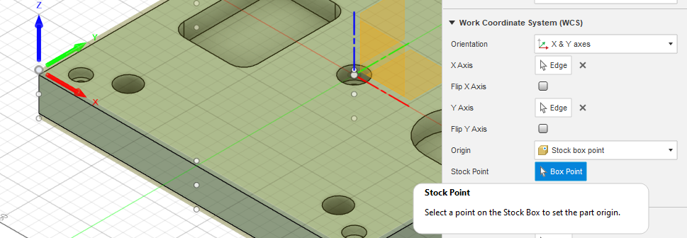
- Click on OK
Only complete the below if the model is already in the correct axis alignment.
- Ensure that the Origin Selection is set to Stock Box Point
- Select the Stock point by clicking on one of the white dots on the stock box point.

- Click on OK
You should now have your model on the machine and a setup shown in the setups
Creating a tool and an operation
For this operation, a simple example of clearing a single pocket will be showcased.
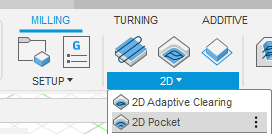
- Select the 2D Operations dropdown and select 2D Pocket
- In the Tool tab and the tool section, click on Select to create a new tool

- Using the list that you had created earlier find the tool that you want to use
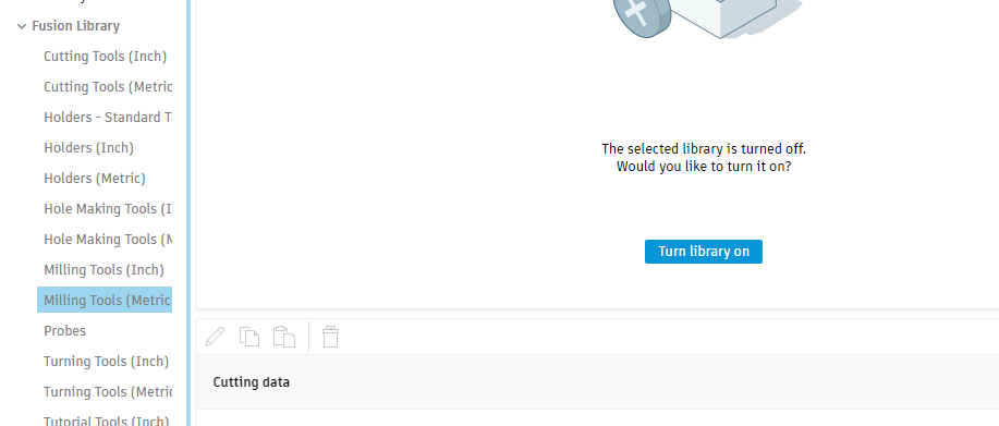
- Select the Fusion Library - Milling tools from the menu on the left and turn on the library if required
- In the filters on the right, select the correct type of mill that you want to create the operation for i.e. Flat End Mill
- Find and select the correct milling bit that you are creating the operation with. IT IS HIGHLY RECOMMENDED THAT YOU MEASURE YOUR MILL BIT TO ENSURE YOU HAVE THE RIGHT SIZE.

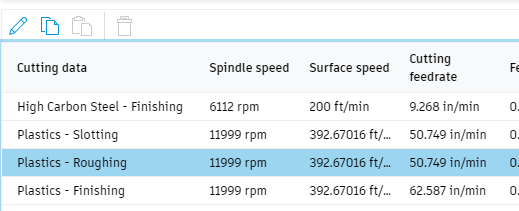
- In the cutting data section select the correct material and operation type that will be completed.
- Click on Select
- Change the coolant type to Disabled from the default that reads Flood

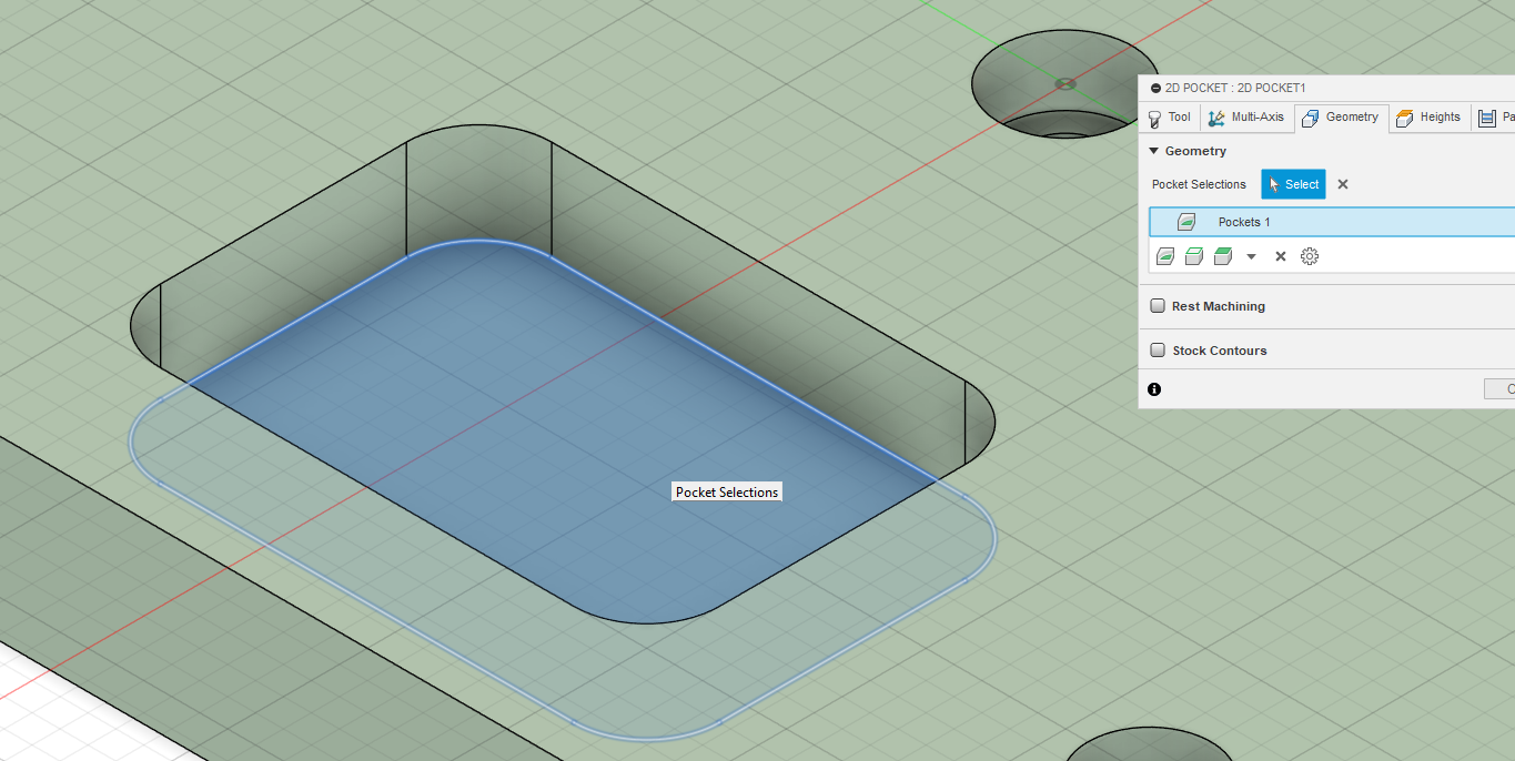
- In the Geometry Tab under the Geometry section, click on Select.
- Click on the model feature that needs to be machined
- In the Heights Tab, check that the clearance height is at least clearing the fixture mounting hardware. Screws through the materials should be fine with a 10mm clearance.

- In the Passes Tab under the Stock to Leave option, take note of the stock that is left for Roughing passes. This should not be selected for finishing passes.

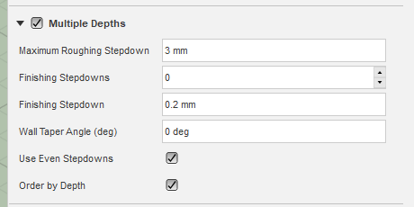
- In the Passes Tab, under the Multiple Depths section, based on the chip per tooth and loading of the bit, select the option and setup the appropriately calculated depth step down.
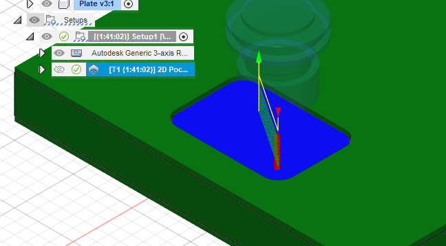
- Confirm that the toolpath generated successfully and that the operation is completed without any issues by reviewing the list of steps under the setup menu.
G-Code Posting
Once all operations are completed to post the G-Code
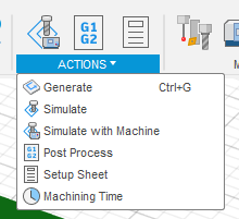
- Under the Actions Section in the ribbon, select the dropdown and choose Post Process option or click on the G1G2 icon.
- Under the Machine and Post section, click on the open folder icon under the Post section
- Click on Fusion Library
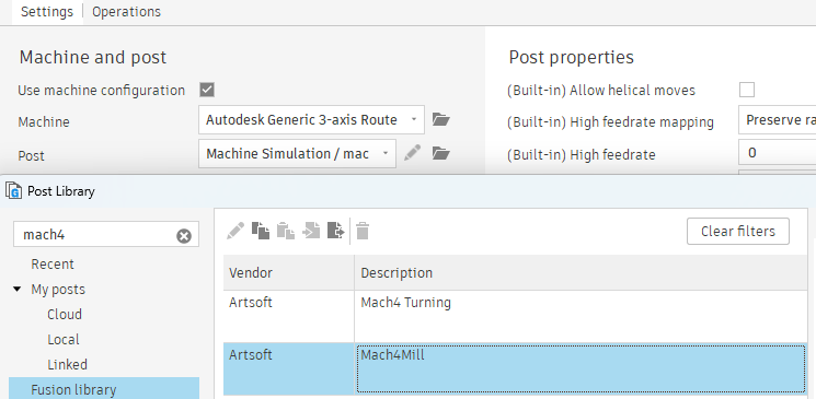
- In the Search Bar at the top search for mach4
- Select Mach4Mill and click Select
- Click on the 3 dots to save to your local library similar to when the machine was downloaded
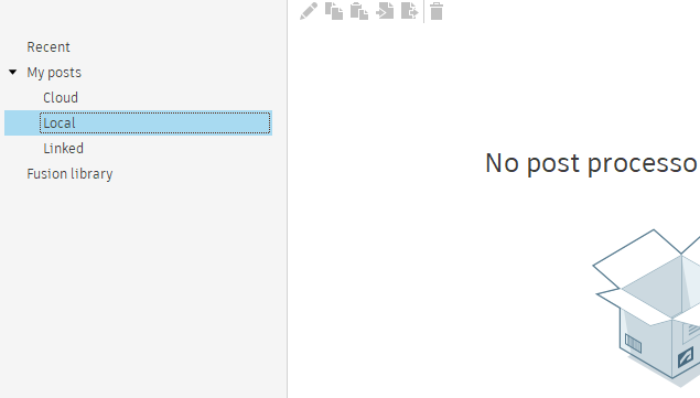
- Click on Select Folder
- Click on Copy to My Posts
- Under the Program Section provide a numbered name only. It is highly recommended that you name your project in the format like in the table below. This will result in a unique number of the format 10010301 that is easily identifiable
| Setup | Part | Group | Revision |
|---|---|---|---|
| xx | xx | xx | xx |
| 10 | 01 | 03 | 01 |
Avid CNC Software
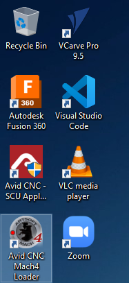
To manage the mill, use the Avid CNC Software from the desktop:
Home the system
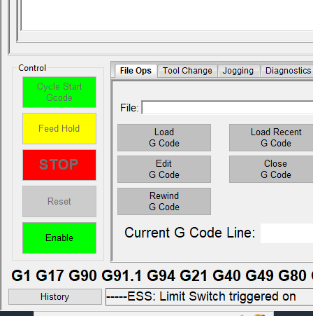
- Regardless of where the machine is, click on Enable
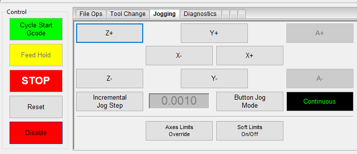
- Select the Jogging Tab and then bring the CNC mill head up all the way using either the Z+or Page Up button on the keyboard.
- Click on Zero Z button
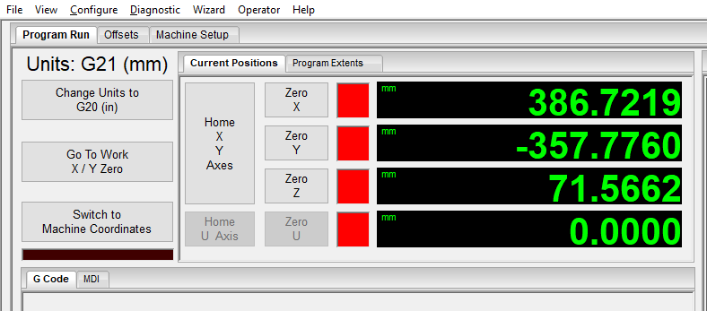
- Click on Home X Y Axes. This should move the machine to the back right and enable soft limits. IFF the machine is not in the back right corner, click the home button again.
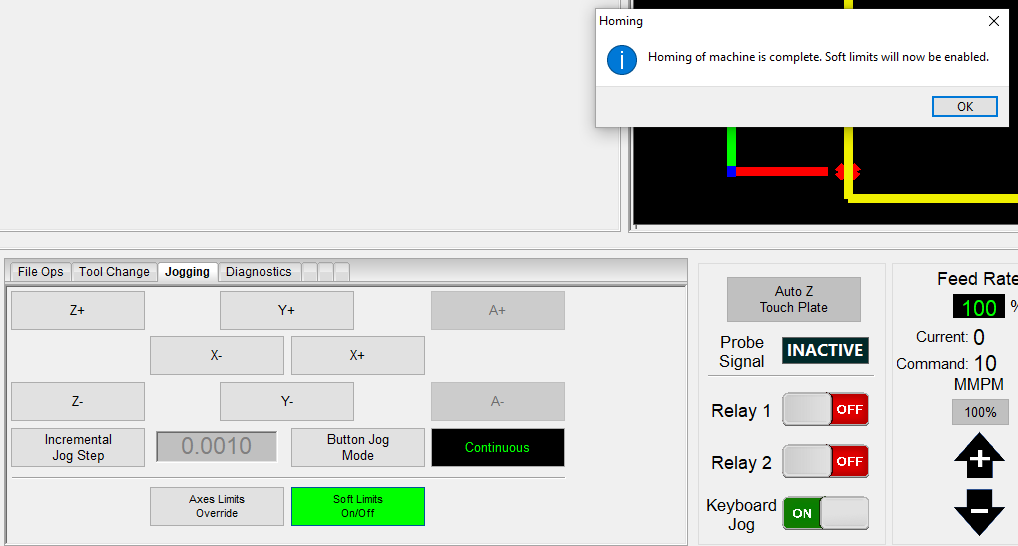
- This completes the system homing process
